Vdo Gauge Wiring Diagram
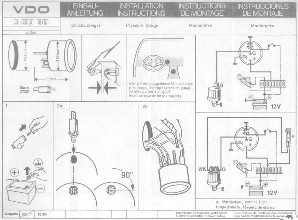
Only connect cables according to the electrical wiring diagram. °f/°c water temperature gauge, use with vdo sender, 12v, spade connection learn more viewline ivory °f/°c water temperature gauge 12/24v &.

Vdo Rpm Gauge Wiring Diagram Wiring Diagram and Schematic
Vdo cockpit electrical water temperature gauge 2 1/16 dia black face.

Vdo gauge wiring diagram. Vdo water temp gauge see more like this. All in one digital display system. #158 or equivalent) 1 4.
Electric tachometer or speedometer w/o odometer. Robertson/stowe some 15 years ago and i do not have a wiring diagram nor are there any adjustments. Get vdo volt gauge wiring diagram pics.i bought my 900 with the cluster as an extra not installed.
Vdo gauges wiring diagrams and boat tach diagram e z go golf cart for boat gauge wiring diagram for tachometer, image size x px, and to view image details please click the image. Here is a picture gallery about boat gauge wiring diagram for tachometer complete with the description of the image, please find the image you need. Viewline 52mm wiring diagram (2014) viewline standard resistive gauges 52mm installation sheet (2014) viewline temperature gauges 12/24 volt (2011) viewline temperature gauges 52mm (2008)
4 8 1 5 11 10 9 8 place the flush mount seal a2c53215640 on the instrument glass. Vdo spin lok clamp or vdo mounting bracket and nuts 1 5. The ground (œ) wire is also run in series, including the light socket ground.
Vdo cockpit vision vdo cockpit international. This is a twin engine set up with two fuel tanks and four fuel gauges. Connect the harness according to the following wiring matrix.
Put the instrument into the drill hole from the back. Diagram a gauge dimensions configuring the vdo tachometer: Aftermarket technical support & troubleshooting.
Vdo volt gauge wiring diagram. Vdo tachometer kit 80mm 0 7000 rpm j11552 just kampers. B) tachometer signal source to the purple lead wire.
Thesamba com gallery vdo volt gauge wiring diagrams performance. Electric speedometer or tachometer w/ odometer/rev counter. Diagram g wiring diagram wiring of power and ground to each gauge illumination wiring.
Necessary to configure the gauge before installation. These instructions are for vdo gauges and accessories only. Now insert the plug into the gauge.
It must be a dedicated ground to insure 3. Vdo electronic speedometer wiring diagram. I installed the vdo oil pressure and temperature gauges in my 1970 vw but will give you the concept on installing them in any vehicle.
Stalled the 2 1/16 (52 mm) gauges. Wire gauges in series from a positive (+) accessory to a source which is not already overloaded with fans, air conditioning, and such. This is part 1 on how to install vdo gauges.
Adjust the instrument so that the gauge is level and fasten it to the stud bolts on the rear side of the panel, With the vdo gps speed sender, there are no cables required. Read these instructions thoroughly before making installation.
† modifications or manipulations to vdo products can affect safety. Coolant temperature oil temperature oil pressure fuel level and speed. Repair & service for aftermarket gauges and accessories.
Always disconnect the battery ground before making any electrical connections. Diagram a vdo tachometer with hourmeter is programmable from.5 to 200 pulses per revolution vdo vdo item description quantity 1. Temperature, pressure or fuel gauge (2⁵⁄₈ [66 mm] diameter) 1 2.
Proper wiring of the vdo voltmeter. Illumination wiring of the speedometer and the 2 1/16 (52 mm) gauges should be done at the same time. Note the inverse polarity protection nose in the process.
Other wiring should be done in whatever sequence is easiest for you. Consequently, you may not modify or manipulate the product! According to the electrical wiring diagram.
At this point, the installation and wiring of the your new vdo voltmeter is. I have single vdo ma fuel but duel resistive oil and water gauges. Veratron flex gauge 52mm nmea2000 12/24v.
If you have additional questions please contact vdo: Two fuel gauges, one on flybridge one in saloon helm. #161 or equivalent) 2 4.
These instructions are for vdo gauges and accessories only. Refer to the wiring diagram, diagram g. Vdo has tried to answer most of your questions regarding installation and trouble shooting of vdo performance instruments.
Vdo volt gauge wiring diagrams 42 draft designs performance instruments troubleshooting boat gauges viewline voltmeter 18 32v black 52 mm amp instrument light power source diagram 8 16v white classic style 60 160 vdc engine oil pressure 80psi fuel tank operating no response from new head. Click here for auto electronic programmable speedometer, electronic. Wiring the gauge (illustration d):
If using the warning led in the gauge and a vdo sender with warning contact wk see wiring information in illustration a 3. † if operating the instrument on power. Diagram c shows how to set the switches for diagram d with alternator, use this table to calculate pulses/revolution & set switches
Vdo water temperature gauge wiring diagram. Do not deviate from assembly or.

Vdo Gauges Wiring Diagrams Vdo Gauge Wiring Diagram Wiring Diagram Mean Design B Mean Design B

Vdo Gauges Marine Diesel Dual Stations Wiring Diagram

Vdo Gauges Marine Diesel Dual Stations Wiring Diagram
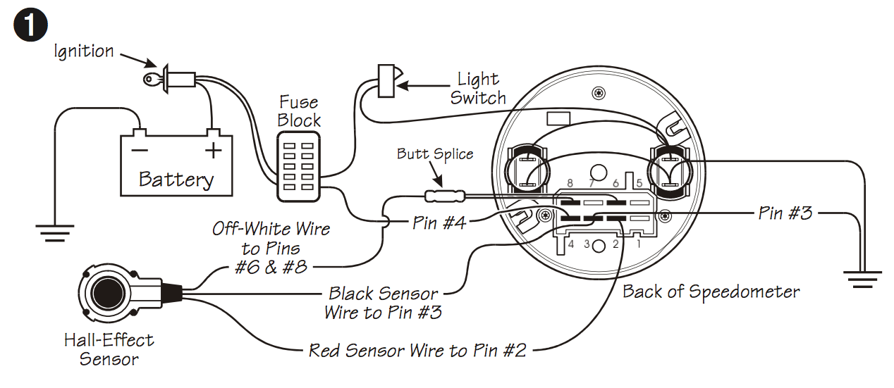
Vw Bug Vdo Electronic Speedo Wiring Diagram

Vdo Senders Wiring Diagrams The view on Wiring diagram
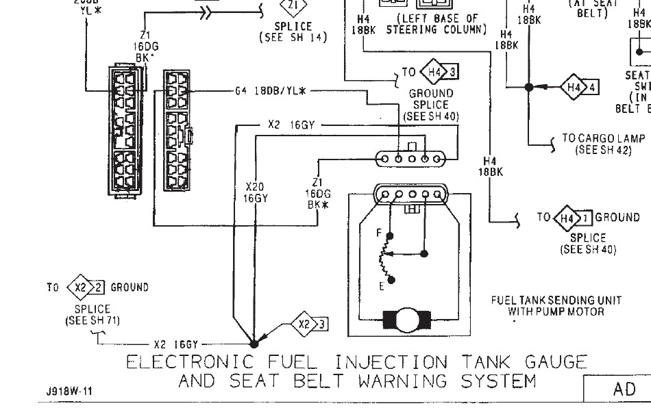
Sea Pro Wiring Diagram Vdo Fuel Gauge schematic and wiring diagram
Vdo Oil Pressure Gauge Wiring Diagram Blue Complete Wiring Schemas

Vdo Gauges Marine Diesel Dual Stations Wiring Diagram

Vdo Electronic Speedometer Wiring Diagram

Vdo Rpm Gauge Wiring Diagram Wiring Diagram and Schematic

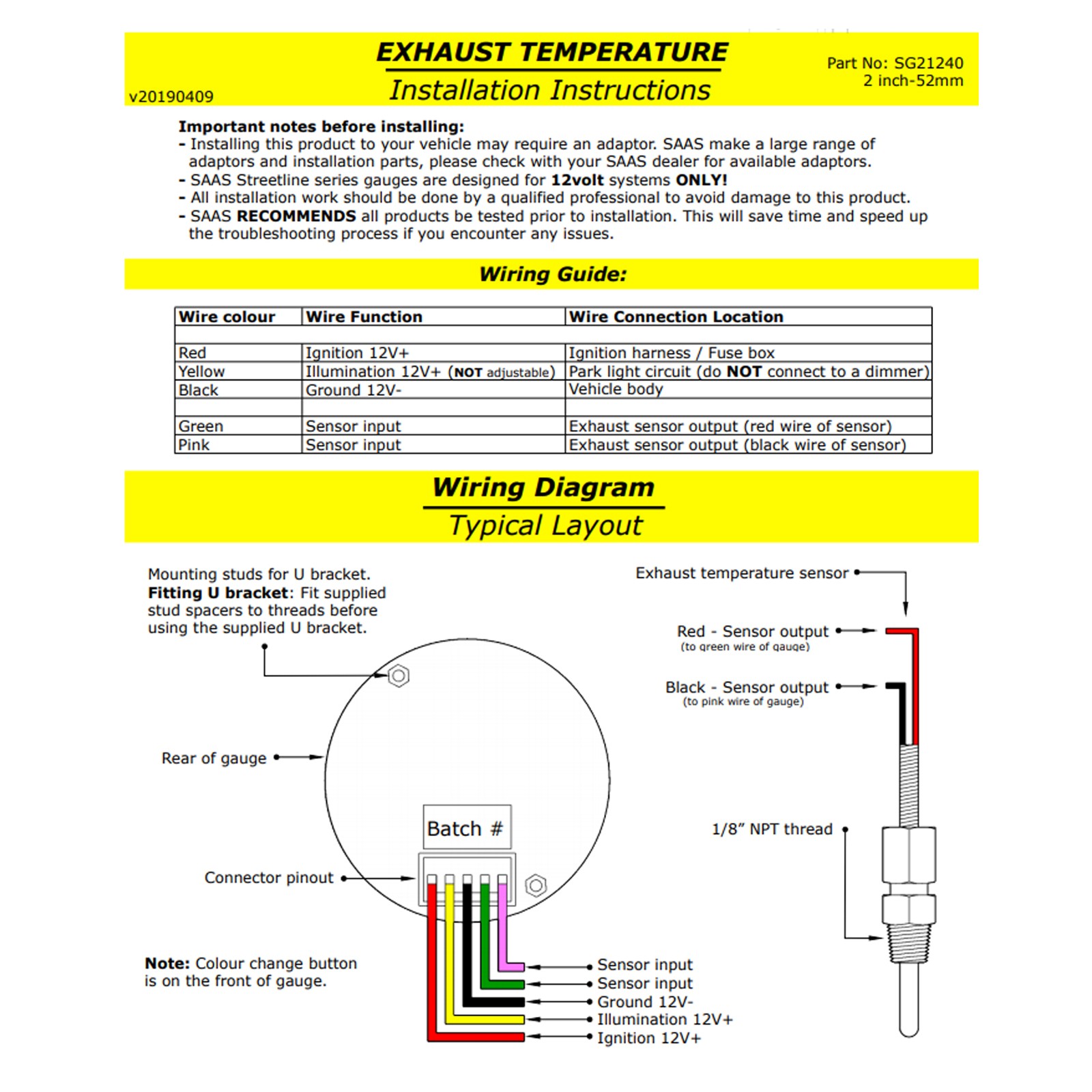
Vdo2c53413386s Temp Guage Wiring Diagram

00858 Vdo Tach Wiring 4 Cylinder Digital Resources

Vdo Oil Pressure Gauge Wiring Instructions My Wiring DIagram
Vdo Oil Pressure Gauge Wiring Inspirational Wiring Diagram Image
Vdo Gaugea2c53436982 Wiring Diagram Complete Wiring Schemas

Vdo Wiring Diagram Complete Wiring Schemas

