Ip Camera Pinout Wiring Diagram
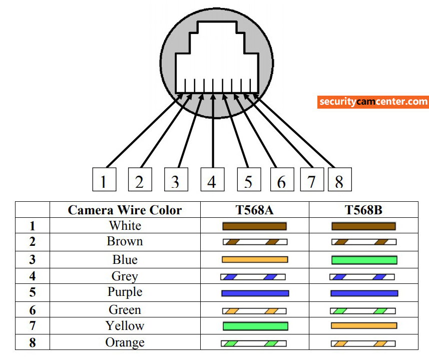
Take a look at the picture below on the left side it s the rj45 pinout t 568b and the right side the dahua ip camera poe pinout color coded wiring diagram. The six wires on the camera are orange, yellow, green, purple, gray, blue, and brown.

Poe Ip Camera Wiring Diagram Cadician's Blog
There’ll be main lines which are represented by l1, l2, l3, and so on.

Ip camera pinout wiring diagram. Below is a description of the basic functionality of each wire associated with the ethernet port pins on your camera: The hikvision ip camera pinout for the value series. Poe ip camera wiring diagram free oasis dl co.
Assortment of ip camera wiring diagram. The distance how far you can set up the cameras depends on the wifi bridges capabilities. There will be principal lines that are represented by l1, l2, l3, and so on.
If you need to connect an external pickup microphone or speaker to the audio camera connect the rca connector to the audio input as. Otherwise the arrangement will not. At times, the cables will cross.
Apart from the example shown above, many of the dahua ip cameras can have a different pinout diagram. According to earlier, the traces in a poe ip camera wiring diagram represents wires. The book features a large amount of.
Take a look at the picture below on the left side it s the rj45 pinout t 568b and the right side the dahua ip camera poe pinout color coded wiring diagram. It contains directions and diagrams for different types of wiring methods as well as other products like lights, windows, and so on. The hikvision ip value series consists of the models listed below.
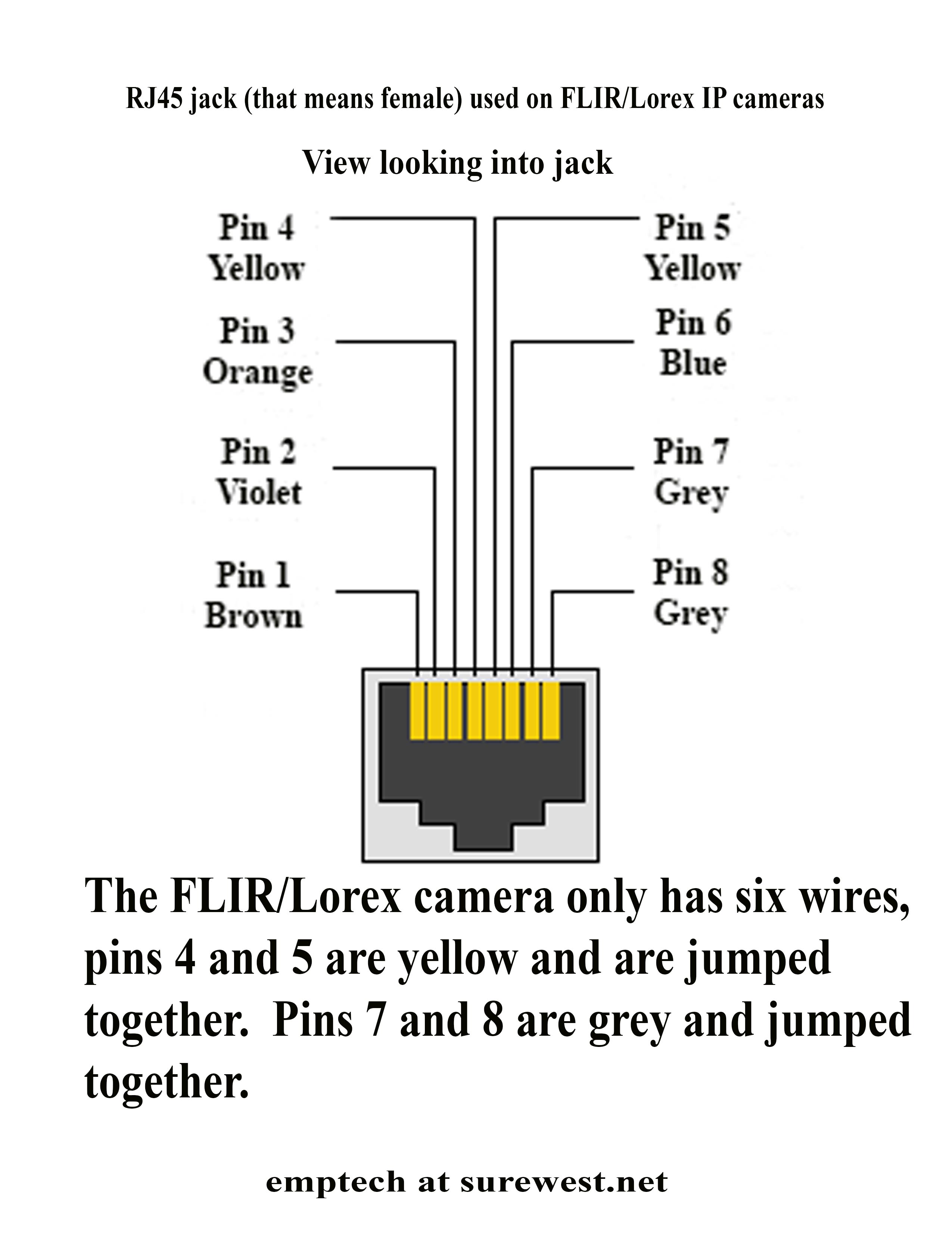
Crimping your rj45 connectors to the ends of your cat5e cable. Wiring diagram contains numerous detailed illustrations that display the link of assorted products. I'm not sure if this will work for all lorex ip cameras, but it worked for mine:
Wiring a lorex ip camera run a cat5 cable to cover the distance between the router and the ip camera. For example, grey wire goes to pin 8, brown wire goes to pin 2, blue goes to pin 1 and so on. The hikvision ip camera pinout for value series the rj45 pinout for pro series hikvision ip cameras security camera wiring diagram por for home rh callingallquestions com poe hikvision image.
Assortment of ip camera wiring diagram. But, it does not mean connection between the wires. Hikvision ip camera rj45 pin out wiring securitycamcenter com code gr closed circuit television diagram system computer network angle electronics png pngegg how to add an a nvr easy step by learn cctv rs 1000 piece s tech logical solutions id 11806519330 configure with ds 7616ni i2 16p 4k poe wdr wide dynamic range dahua pinout guide 2nd.
I also am looking for the pinout. It contains directions and diagrams for different types of wiring methods as well as other products like lights, windows, and so on. These models should have the pinout (wiring diagram) shown on the first picture.
However, it does not imply link between the wires. As stated previous, the lines in a poe ip camera wiring diagram signifies wires. Cat5e wiring diagram for ip camera.
Luma ipc pinout chart in certain situations, you may need to cut the tail of a luma ip camera (or perhaps someone already cut it). Injunction of 2 wires is generally indicated by black dot to the intersection of two lines. Make the connection as shown on the illustration.
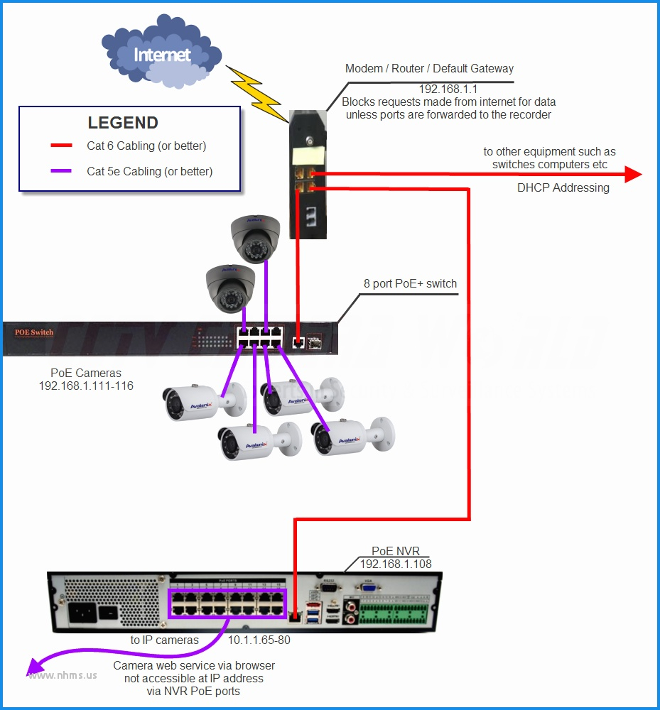
Poe ip camera wiring diagram power over ethernet poe technology enables powering ip surveillance cameras through the transfer of dc electrical and saves money by eliminating the expense and difficulty of direct electrical with poe power can be supplied either by a poe switch or from a poe injector a small power supply placed between a switch and a. With this sort of an illustrative guide, you’ll have the ability to troubleshoot, avoid, and total your projects without difficulty. White/orange, orange, white/green, blue, white/blue, green, and white/brown, brown.
For example, the gray wire goes to pin 8, brown to pin 2, blue to pin 1. Sometimes, the wires will cross. A wiring diagram is an easy visual representation of the physical links and also physical layout of an electric system or circuit.
In such cases, you need to know how to wire it. If you adopt wall mounting, you can also take the below procedure as a reference. Collection of ip camera wiring diagram.
May 14, · this is step 3 in the process of installing your ip camera system: Injunction of two wires is usually indicated by black dot at the intersection of two lines. A wiring diagram usually provides information regarding.
When i cut of the female sockets i discovered that there were only six cat5e wires instead of the four twisted pairs. The connection is as shown in the illustration. Pin functions the pin functions are as follows:

Hikvision IP Camera RJ45 PinOut (wiring) —

Rj45 Wiring Diagram Poe / Dahua Ip Camera Color Code Pinout For The Ip Megapixel

ip camera poe pintout Best way to IP Camera connector punch

Hikvision IP Camera RJ45 PinOut (wiring) —

Schematic 4 Wire Security Camera Wiring Diagram
Zmodo Knowledge Base How to Repair The Cable on a Simplified POE Camera

Poe Ip Camera Wiring Diagram Cadician's Blog

IP camera Closedcircuit television Wiring diagram System Computer network, Ip Code, angle

Dahua Camera IP POE pinout diagram YouTube

Ip Camera Wiring Diagram Download Wiring Collection

FLIR IP dome camera water damage in RJ45 connector using POE Installation Help and Accessories

Dahua camera RJ45 pinout guide (wiring diagram) —

PoE IP Camera Wiring Diagram Details AlfinTech Computer

Ip Camera Wiring Diagram Download Wiring Collection
Ip Wiring Diagram Top Security Camera Wire Color Diagram Luxury Outstanding Ip Camera


